Short story: My two year old helped me burn a flight controller trace right out of the board. It's fixed now.
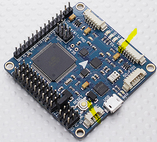
Longer story: I was trying to integrate the GPS and RF Radio (433 MHz for data, not the Receiver/Transmitter) to my flight controller and I didn't quite understand what was going on. When I plugged in via USB and powered VCC with 5V, everything worked just fine. When I powered the board with the LiPo (11V), the GPS did not work. I had thought that the connector holding serial port 1, 2, and 3 was powered from the 5V regulator, but this turns out not to be the case. It is directly connected to the pins shown below in yellow highlighter, labeled VCC and GND. In other words, the left yellow blob is connected to the right yellow blob. I power the Flight Controller with 11V on the top left yellow pins in the picture below. It gets regulated down to 5V, but not until after it hits the power on the connector for serial port 1, 2, and 3.

In the course of my investigation, I was using a multimeter to see what was connected to what. In hindsight, it would have be a lot smarter to use the ohm-meter part of it rather than the volt-meter part, but oh well. I was trying to see if I got 11V or 5V between the VCC and GND on the serial port connector. My two year old bumped me at the exact wrong time and I let the magic smoke out. Electronics don't work very well once the magic smoke escapes. I shorted GND to VCC with my multimeter probe inside the serial port connector by making contact with both pins. It immediately sparked, burned, gave off smoke, and left me feeling less than smart. Take a look at the burned trace below.
.jpg)
Near the top of this photo you can see the VCC line burned right out of the board, with a big chunk burned away. Interestingly enough, the GND trace burned, some of it was exposed at the top of the board, but it still had electrical continuity. Thankfully, the power traces appear to be on the outside of the board, so it didn't damage anything else. Everything else on the 5V side of the voltage regulator appears to be fine.
After some thought, I decided to route 5V from the I2C port to the Serial 1, 2, and 3 connector, as it is both regulated and does not go through the Atmel AVR microcontroller, which means there isn't nearly as big of a current draw concern. The screenshot below highlights in yellow the new intended connections.
I took the board in to the lab at work, as I don't have a big magnifying glass nor an awesome soldering iron (they have a seriously awesome one with super small tips). I tried to solder some bus wire from the I2C port to the Serial port for about 40 minutes without good success. The lab guys took pity on me, and about 18.5 seconds later, it was soldered on there good and tight. Thanks to Mike L. and Ben B. for getting me set up and soldering this. I'm not great with super-tiny details like this, but they knocked it out in a hurry. See the picture below for the completed patch, using red bus wire. It is glued down to the board to prevent mechanical stress on the soldering, as losing this wire means losing power to the GPS and the 433 MHz data radio on the quadcopter.
.jpg)
Testing with the GPS shows that everything is working as expected. This is the best of all possible mishaps, as it probably saved my GPS from getting burned up, and allowed me to route 5V to the appropriate places.
The only unfortunate thing is after all of this, Windows 7 and my flight controller are having some sort of disagreement. We're operating along with mission planner talking no problem, when suddenly, the serial port (VCP) goes away. Gone. Nothing left. I don't know why. Reboots and reinstalls haven't fixed it. I guess that's an issue for another day. For now, I'm just glad my GPS is (ostensibly) working. It looks like it based on status lights.... I can't prove it until I integrate the 433 MHz radio or get USB back up.
The only unfortunate thing is after all of this, Windows 7 and my flight controller are having some sort of disagreement. We're operating along with mission planner talking no problem, when suddenly, the serial port (VCP) goes away. Gone. Nothing left. I don't know why. Reboots and reinstalls haven't fixed it. I guess that's an issue for another day. For now, I'm just glad my GPS is (ostensibly) working. It looks like it based on status lights.... I can't prove it until I integrate the 433 MHz radio or get USB back up.