Showing posts with label Flight Controller. Show all posts

27 January 2014

Compiling and Uploading MegaPirateNG Firmware to the Quadcopter

The following is the bare minimum to compile and upload the MegaPirateNG firmware to your Flight Controller. Refer to this site for the full tutorial.

The bare minimum highlights:
1) Download the source code. Circa January 2014, I used ArduCopter-MPNG V3.0.1 R2.

2) You need a special version of the Arduino environment. I used this one.

3) There is a step where you replace the Arduino environment's "pde.jar" with the one that comes with the MegaPirateNG source code. Do not skip this step. Make sure to do it with the Arduino IDE closed.

4) Open "ArduCopter.pde" in the Arduino IDE.

5) If you use the Hobby King V2 Flight Controller like I did, you  need to modify the firmware, as this board does not use Pulse Position Modulation (PPM), but used Pulse Width Modulation (PWM) instead. The change to the firmware is minor, and shown below. Dig in and find the file ardupilot-mpng\libraries\AP_HAL_MPNG\RCInput_MPNG.cpp and modify it as shown in the pictures below. Red text is removed, and green text is added.

This is what the firmware looks like before the change:


This is what the firmware should look like after you have made the change to use PWM.

6) Install the Virtual COM Port (VCP) version of the FTDI driver. There are other versions, so check this page if you're not using Windows 7 64-bit like I am.

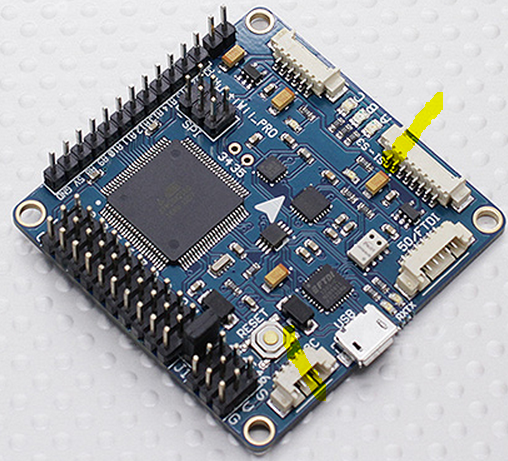
7) Hook up your Flight Controller via USB. Windows should recognize it and you should get some red blinking lights on the Flight Controller board.

8) Choose the proper serial port. Mine was COM3. Yours may be different.


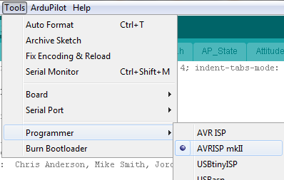
9) Choose the proper programmer. AVRISP mkII worked for me.


10) Choose the proper target board. My Flight Controller has an ATMega 2560 onboard.


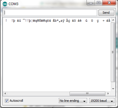
11) If you open the Serial Monitor under Tools, you should see some output coming from the board every second or so. Don't worry that it looks like gibberish at the moment. (We'll talk about that gibberish more next time.) See picture below.


12) Compile
To start the compilation:


Compiling:


Done Compiling:


13) Upload. Push this button while connected to upload. Be patient; it's a big sketch.


14 When the upload successfully completes, you should be able to open Mission Planner and connect. This is a tremendously awesome free GUI for configuring, controlling, and monitoring your quadcopter. We will get more in to this next time, but for you overachievers out there, feel free to go ahead.. You should be able to see all sorts of cool output from your connected flight controller. We're almost ready to arm and spin the motors.


17 January 2014

Receiver to Flight Controller

The flight controller is the brains of the quadcopter. It has sensors that determine the pitch, roll, yaw, altitude, and acceleration of the quadcopter. Mechanically fix the flight controller to the frame, tell the flight controller what level looks like based on how you mounted it to the frame, and tell it how your motors are arranged. (We will cover these things a bit later.) The flight controller senses if the quadcopter tips, and controls the motors to correct it and level out the quadcopter. Quite frankly, this is amazing. It takes a lot of the complication of flying out, and makes it stable and easy to fly.

In order to do this, the flight controller has to be hooked up to the receiver appropriately. There are six lines that matter for this:
1) Yaw
2) Throttle
3) Pitch
4) Roll
5) +5V
6) Ground

On the flight controller I bought, there is silk screen showing what to connect to where, but the silkscreen is wrong. The wrong labels are repeated on the hard case I bought. Pitch, Roll, and Throttle are wrong. Here is the wrong silkscreen on the flight controller board:


Here is the wrong silkscreen on the hard case.


It took me a long time to figure out that the silkscreen was wrong, as I completely trusted it. In the end, I was able to figure it out because when I tipped the quadcopter while it was turning the rotors on very low throttle, the wrong motors would cut out. The idea here is if you have it in a stabilize mode and you tip it so one rotor is up, that rotor should slow or stop because the unit is trying to level out. So experimentally, I determined the layout. Here's the actual layout for the board I have:

Remember, the silkscreen is wrong, so it should read, starting with the yellow wire:

Yaw
Throttle
Pitch
Roll
+5V
Ground


As you can see above (spelled out for the colorblind), wire colors I chose are:
Yaw--Yellow
Throttle--White
Pitch--Blue
Roll--Red
+5V--Orange
Ground--Brown


These wires plug in to the receiver. Based on the color scheme I chose, and the channels I have selected on the transmitter, here is how I have wired up the receiver-flight controller connection at the receiver side:


Bat Orange and Brown (Inside has nothing, Middle is Orange, Outside is Brown)
   6  White -- Throttle
   5  Nothing
   4  Yellow -- Yaw
   3  Nothing
   2  Blue -- Pitch
   1  Red -- Roll
Remember that the signal pins are the inside ones (the pins nearest the channel number label).

As I spent so much time debugging the Receiver to Flight controller, and thinking I had something wrong, I'm documenting the full interconnect. The sticks on my transmitter are set up like this:

  • Pitch (Blue), Channel 2, left stick forward and back
  • Yaw (Yellow), Channel 4, left stick left and right
  • Throttle (White), Channel 6, right stick forward and back
  • Roll (Red), Channel 1, right stick left and right

The next thing to hook up is the ESC's to the motor controls on the Flight Controller. There are four of them, and you have to get the right one in the right place (you could modify the firmware to change which one plugs in where, but it's a lot easier in my mind to simply plug the right one in to the right place). Again, you have to experimentally determine which one is which. I chose the "+" configuration, so here is what it turned out to be for me:

Note that as odd as it seems, according to the silkscreen there is no "4" slot.
Front 6
Back  2
Right 5
Left  3

Looking back at this blog post, it doesn't seem nearly as hard as it was in real life. The hardest part was that I kept thinking I did something wrong on the receiver end because of the problem with the silkscreen. Now that I know how it should go, wiring this up could be really fast and painless. :-)


08 January 2014

Lessons Learned

Last post as I was trying to prove that the GPS worked after the board modifications, I couldn't get the USB connection to work with Mission Planner. I thought I had toasted my Flight Controller board yet again.

The COM port, COM3, had just disappeared from my laptop. Nothing I did could bring it back. I got an automatic Windows Update minutes before I plugged it in and it did not work. This was suspicious. I did a bunch of things to the PC to try to make it work:

  1. I rebooted the PC multiple times
  2. Updated to the latest Mission Planner
  3. Reinstalled Mission Planner from scratch
  4. Reinstalled the Virtual COM Port driver 
  5. Hard removed COM3 and reinstalled the Virtual COM Port driver
  6. Hard reinstalled FTDI drivers by themselves
  7. I thought that maybe I had connected it to a low-power USB port and there just wasn't quite enough juice to get it working. I tried all the USB ports on the laptop to no avail.
None of these things helped, so I quit for the night thinking it might be broken for good.

After some thought, I realized that the power rails in a USB connector are longer than the signal rails. It makes sense that they are physically engaged before the signal rails are.

Silly me. In all my debugging, I had never reseated the Flight Controller end of the USB cable. I had done it all at the laptop end many times. One quick reseat and it was working fine. I did four things differently the time it worked. I'm listing them all, but I'm pretty sure it was that the USB connector wasn't all the way plugged in to the Flight Controller.
Differences:

  1. Waited 20 minutes without anything plugged in (heat? built-up charge? gremlins?)  
  2. Reseated the USB cable at the Flight Controller end
  3. I connected to the laptop via USB after connecting to the Flight Controller..... it really shouldn't matter.
  4. Held down the Flight Controller reset button while I plugged USB to the laptop, but I don't think that had anything to do with it. 

 I just wanted to mention it in case I'm wrong. One of those four things (or some odd combination plus reinstalling all the software above) did it. I'm reasonably confident it was reseating the USB cable at the Flight Controller.

So the long and short of it is that the Flight Controller fix made the GPS module work. This is good progress.


One thing that puzzles me is how good a GPS signal I get indoors. This is a cheap GPS module, but I'm seeing 7 satellites indoors. Can that be possible? The GPS units I use at work are orders of magnitude more expensive and nicer, and they take WAY longer to get a fix, and certainly can't function indoors. I'm wondering if this has something to do with the overall precision of the GPS unit. The ones at work claim to be very accurate when they have a fix. This one, not so much. Don't know. More on it later if I dig into it.

Unable to Connect


I thought that there was something else wrong with the Flight Controller, as I was unable to successfully arm it. Once I got it connected, I was able to use Mission Planner to figure out why it would not arm the ESCs. The error was "RC Not Calibrated". This means it did not think the Radio Control (Transmitter) was calibrated. I calibrated it and wrote the settings down to the Flight Controller, but it still came up as Not Calibrated each time I cycled power. I wondered if maybe the USB port wasn't kicking out enough power to write to the EEPROM or if there was something else wrong with the Flight Controller. After a lot of worry, it turns out that the trim for the throttle was WAY too high. This meant that even at the stick's minimum it couldn't get low enough for Mission Planner to be happy with it. I actually have two trims on my Transmitter, one a fine control, one a gross control. Apparently the gross control had been turned a lot. After fixing that, it armed no problems.

Next time we'll cover connecting the Flight Controller to the Receiver.

07 January 2014

Flight Controller Oops!

Large current sources and toddlers don't mix in happy ways.

Short story: My two year old helped me burn a flight controller trace right out of the board. It's fixed now.

Longer story: I was trying to integrate the GPS and RF Radio (433 MHz for data, not the Receiver/Transmitter) to my flight controller and I didn't quite understand what was going on. When I plugged in via USB and powered VCC with 5V, everything worked just fine. When I powered the board with the LiPo (11V), the GPS did not work. I had thought that the connector holding serial port 1, 2, and 3 was powered from the 5V regulator, but this turns out not to be the case. It is directly connected to the pins shown below in yellow highlighter, labeled VCC and GND. In other words, the left yellow blob is connected to the right yellow blob. I power the Flight Controller with 11V on the top left yellow pins in the picture below. It gets regulated down to 5V, but not until after it hits the power on the connector for serial port 1, 2, and 3.

In the course of my investigation, I was using a multimeter to see what was connected to what. In hindsight, it would have be a lot smarter to use the ohm-meter part of it rather than the volt-meter part, but oh well. I was trying to see if I got 11V or 5V between the VCC and GND on the serial port connector. My two year old bumped me at the exact wrong time and I let the magic smoke out. Electronics don't work very well once the magic smoke escapes. I shorted GND to VCC with my multimeter probe inside the serial port connector by making contact with both pins. It immediately sparked, burned, gave off smoke, and left me feeling less than smart. Take a look at the burned trace below.

Near the top of this photo you can see the VCC line burned right out of the board, with a big chunk burned away. Interestingly enough, the GND trace burned, some of it was exposed at the top of the board, but it still had electrical continuity. Thankfully, the power traces appear to be on the outside of the board, so it didn't damage anything else. Everything else on the 5V side of the voltage regulator appears to be fine.


After some thought, I decided to route 5V from the I2C port to the Serial 1, 2, and 3 connector, as it is both regulated and does not go through the Atmel AVR microcontroller, which means there isn't nearly as big of a current draw concern. The screenshot below highlights in yellow the new intended connections.


I took the board in to the lab at work, as I don't have a big magnifying glass nor an awesome soldering iron (they have a seriously awesome one with super small tips). I tried to solder some bus wire from the I2C port to the Serial port for about 40 minutes without good success. The lab guys took pity on me, and about 18.5 seconds later, it was soldered on there good and tight. Thanks to Mike L. and Ben B. for getting me set up and soldering this. I'm not great with super-tiny details like this, but they knocked it out in a hurry. See the picture below for the completed patch, using red bus wire. It is glued down to the board to prevent mechanical stress on the soldering, as losing this wire means losing power to the GPS and the 433 MHz data radio on the quadcopter.


Testing with the GPS shows that everything is working as expected. This is the best of all possible mishaps, as it probably saved my GPS from getting burned up, and allowed me to route 5V to the appropriate places.

The only unfortunate thing is after all of this, Windows 7 and my flight controller are having some sort of disagreement. We're operating along with mission planner talking no problem, when suddenly, the serial port (VCP) goes away. Gone. Nothing left. I don't know why. Reboots and reinstalls haven't fixed it. I guess that's an issue for another day. For now, I'm just glad my GPS is (ostensibly) working. It looks like it based on status lights.... I can't prove it until I integrate the 433 MHz radio or get USB back up.


31 December 2013

Flight Controller Paper

I wrote a paper on Flight Controllers for a class at Syracuse University. An extremely condensed version in PowerPoint format is also available. See links below.

Abstract:
Multirotor unmanned aerial vehicles are transitioning from the niche hobbyist domain to “the ­­next big thing.” Until recently, price, component technology, software, and domain-specific expertise kept most people from experiencing multirotors directly. This is about to change.  Price, hardware, software, and the technical expertise involved have combined to create a confluence of opportunity. While the potential multirotor field is vast, the technology is varied, compatibility issues abound, jargon runs wild, the literature is informal, and governmental regulation is uncertain. We leave government regulation discussions to others, instead focusing on the “brains” of a multirotor system—the flight controller. We discuss the pedigree, capability, and compatibility of contemporary flight controllers and explore the architecture of a modern, low-cost, open-source flight controller. We give a very brief “getting started with multirotors” checklist and demystify the lingo. Finally, we consider the future of the multirotor field. Multirotors are now within reach of the masses. Prospects for multirotors are very bright, and are poised to grow substantially.


Take a look!