27 May 2015
Near-Name Collision in The Cold Heart of Space
I just noticed there is a band that made an album (or at least half of one... looks like they have one side of a cassette tape filled... not sure if it was a joke or not, didn't listen to the music) that has a very similar name to my blog. Just to clarify, I'm in no way related to the band, and they are in no way related to me. But they chose an awesome name. :-)
26 May 2015
And Now Back to Our Regularly-Scheduled Program...
Wow. If you haven't noticed, this site was inaccessible via www.thecoldheartofspace.com for almost six months. You could still get to it via the blog address, but who knew that address anyway?
Why? you ask. Well, in my quest to do things super-cheaply, I made a serious blunder. But you'll have to read the backstory first...
Backstory:
I first registered this domain via register.com. They were okay. Things worked. It wasn't bad. They gave me a super deal on the first year. Then, the next year, they wanted to raise the prices to ridiculous levels. I balked, and decided to transfer to the cheapest thing I could find. It turned out I chose 1and1. Big mistake.
First, the transfer process from Register.com was tedious, and didn't actually work. I had to call them to enable transferring, but by the time 1and1 (or me, not sure who was the weak link) got around to actually pulling the trigger on the transfer, the code register.com gave me no longer worked. And I made the mistake of updating my whois settings (because I had moved), and it locked me out of any other changes (such as transferring to a new registrar) for 2 weeks. Great. So the domain name actually expired, and rather than pay the insane oops-I-let-it-expire-and-now-I-want-it-back extortion fee, I simply waited the 35 days for the ransom era to end. Yeah, I'm cheap, but for a silly little blog that's read by like 2 people ever, I'm not paying hundreds of dollars to get my domain name back. Tough luck. :-) So first lesson learned, I don't think register.com is actually an a registrar. I think they are a reseller. Probably should have gone with an actual registrar. Anyway, after the domain name expired and the ransom period was over, I purchased the domain name via 1and1.com. The price was great, but for some bizarre reason, I could not make it point appropriately to my blog. They apparently don't like google blogs, or something. There was a guide on the web that said "here's how to work around this and make it work". I tried to follow it again and again, but with no success. They want you to add subdomains to verify with google that you can edit records to make sure you own the domain and what not. Well, with register.com, that sort of thing would happen within an hour or two. With 1and1.com, it took over 4 days. Craziness. I got sick of trying to mess with it , so I decided to move it to Google domains. 1and1.com wouldn't let go of the domain and actually prevented me from transferring it for 90 days. When it finally went through, ONE SIMPLE CLICK (and typing in my blog address) on Google Domains and my blog was back to being pointed at by the domain name of my choice. Note I did have to go back into blogger settings and tell it to redirect from the blog address to the domain name I chose, but that was easy. Google only charged me $12 for a year, and that includes whois privacy. And it's simple to use. I can customize what I need and don't have to go through an AGONIZING web interface. The difference is night and day.
No longer backstory:
So, long story short, be careful who you choose to register your domain name through. I'm very happy with Google Domains. Register.com was okay, but did the jack-up-the-prices-like-crazy trick after one year. 1and1.com was agonizing. And I never successfully made it point my domain name to my blogger blog. Your mileage my vary, but I'm never going back. :-)
Oh yeah. One more thing to yell about. 1and1.com had the craziest interface for DNS. I simply COULD NOT set things up. It was like they put boxing gloves on my hands and told me to type the collective works of Bill Shakespeare. In an hour. It was brutal. I felt like screaming each time I tried, unsuccessfully, to get my simple little blog on the interweb again.
23 September 2014
Learning More Git
A quick recap on the last post to refresh memory. We'll save more details on git for the next post.
My master repository is going to use the alias "upstream" and my fork of it will use the alias "origin". I will be doing work in the develop branch, and I will be using the origin https://github.com/karlmortensen/learn-git
My master repository is going to use the alias "upstream" and my fork of it will use the alias "origin". I will be doing work in the develop branch, and I will be using the origin https://github.com/karlmortensen/learn-git
| Command | Result |
| git init | Make local machine current directory into a git repository. |
| git clone URL | Clone my fork of this repo from GitHub down to my local machine |
| git status | Show which files are modified and which are staged to commit |
| git status -s | Shows simplified view of git status |
| git checkout -b new_branch | Creates new_branch and sets it to be the branch I am working on |
| git add somefile.txt | Adds somefile.txt to the staged to commit list |
| git diff updatedfile.txt | Shows diff between the file on local machine and committed version |
| git branch | Show the branch I'm working on right now |
| git commit -m "My message here" | Commits changes to the branch I'm working on right now |
| git push origin master | Push committed changes to the origin repo, master branch |
| git fetch upstream | Grab the lastest-greatest from the upstream master |
| git merge upstream/master | Merge the fetched latest-greatest into my local clone |
Learning Git
I'll admit it: I had a hard time with git.
I've used Perforce, ClearCase, Mercurial, and even my own super-ugly flavor of copying directories to "backup", "old", "_saturday_night", or "before_I_put_the_feature_in" directories. None of them comes close to the mental-model struggle I've had learning git. So, in an effort to concatenate my learning, here you go. (If you don't care to learn how to use the distributed source control method that seems to be the source control most frequently used among open-source developers on the web, by all means, skip this post and go watch TV.)
So here goes. Feel free to comment on where things could be clearer. I'm no expert yet.
I started by making an account at GitHub. For other reasons, I downloaded Cygwin, and included git. You don't have to do that. You can simply download the git client if you like, based on your particular operating system. Install it and go to the command line. I'll wait here.


Now, having reviewed all my work and decided it's worthy, I "push" it to my origin with the following command: "git push origin feature_1"


I've used Perforce, ClearCase, Mercurial, and even my own super-ugly flavor of copying directories to "backup", "old", "_saturday_night", or "before_I_put_the_feature_in" directories. None of them comes close to the mental-model struggle I've had learning git. So, in an effort to concatenate my learning, here you go. (If you don't care to learn how to use the distributed source control method that seems to be the source control most frequently used among open-source developers on the web, by all means, skip this post and go watch TV.)
So here goes. Feel free to comment on where things could be clearer. I'm no expert yet.
I started by making an account at GitHub. For other reasons, I downloaded Cygwin, and included git. You don't have to do that. You can simply download the git client if you like, based on your particular operating system. Install it and go to the command line. I'll wait here.
Git command line in Cygwin
If you can type git and press enter and then see something like the above, you are ready to start. If not, play it again Sam.
If you have a directory of files you'd like to turn into a git repository, use git init
This is not what we're doing in the tutorial though. :-)
Log in to your GitHub account. I just logged into mine and created a repository: https://github.com/karlfakegitaccount/learn-git All it has in it is a Readme.md file. I'm going to call this repository I just made my "master" repository or my "upstream" repository. I've seen both aliases used for this one and don't know which is more common.
Conceptually, this is the repository where I will release new versions of my software from. To get released, software must be merged into this repository that is stored on GitHub. This is an arbitrary decision I have made, but it seems most folks make the same decision.
Now, for day-to-day working, I'm going to create a "fork" of this master repository that I'm going to call "origin". This fork will go in my day-to-day GitHub account, karlmortensen. (I made an extra account so I could show how to get changes back into some external baseline...) A fork is an exact copy of everything at a specific point in time. It seems "origin" is general parlance for the fork that you use to save your day-to-day work into. When the time comes, we will ask the master repository owner (karlfakegitaccount who happens to be me, as I just created it a few minutes ago) to "pull" changes from "origin" (karlmortensen account) to "master" (karlfakegitaccount). This is the only path I've seen for getting changes into the master repository (repo).
Do you mind if I drop the quotes around origin, master, and upstream? Dropped!
To get a working copy in my regular karlmortensen account, I simply use the GitHub GUI. I logged in to my regular GitHub account (karlmortensen), and used this search: "learn-git user:karlfakegitaccount". This got me a link to the master repo of the project I'm going to be contributing to. Go into the project and press the button "Fork". For those following along at home, go ahead and fork my karlfakegitaccount/learn-git repo. Your screen should look just like mine except the user name at the top is going to be your user name. The one on the left will look exactly the same.
It should now look like this (with the accounts changed to your accounts, of course):
Bear in mind I now have two copies of this repo on GitHub, the master and the origin. They are in different GitHub accounts. I do not have a copy on my local machine yet.
To get a copy on my local machine, see the "HTTPS clone URL" highlighted in yellow in the picture above? Copy that text to the clipboard, go to the command line where you want to "clone" this fork to, and type "git clone URL" where URL is the pasted text. My example:
Now, you can see the file created in the master is populated on my local machine:
Before I start work, I want to make a new branch so I can commit it from that branch. It should make things easier (and when I took the screenshots, I forgot to do this, so when I went to commit, I was still on the master branch... not what I wanted, so I fixed it and didn't update the screenshots... from here on out, where it says "on branch master" read it as "on branch feature_1"). I used the command "git checkout -b feature_1". Feature_1 is the name of the branch that I just made and checked out. So I'm working in this branch now.
Now I am finally set up to begin contributing to this project.
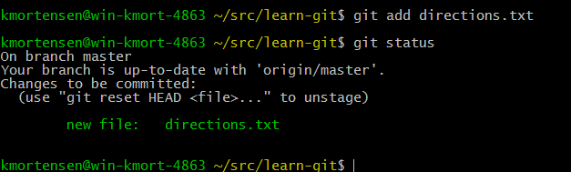
My first task was to implement a file called "directions.txt" explaining how to get to Oz.
Whew. So I put the file in the folder. Typing "git status" shows that there is an "untracked" file in there. I want git to track this file, so I use the command "git add directions.txt"
Now it shows up as tracked.
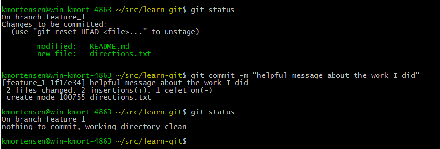
This means that when I commit changes to git, this one will be among them. I also got the task to update the readme file. So I did.
So README.md is modified. Use git add to add it to the list of files staged to be committed.
Now that we have all this work accomplished, let's commit it to git so we don't lose it. Use git commit -m "helpful message about the work I did" with the quotes included this time.
The act of committing saved the changes to git on my local machine, but did not affect GitHub at all.
We need to set up one more thing:
Basically, I just taught git what the aliases that I call my different repositories are. The command with the "rm" in it removes the blank origin statement from the list. Then I add in origin and upstream, both pointing at where I want them to be. The command "git remote -v" allows me to see what the alias mapping is currently set to.
If this is your first time committing, you'll get a message asking for your name and email address. Provide it in the format the message shows. This sets up your local machine to talk to GitHub easier.
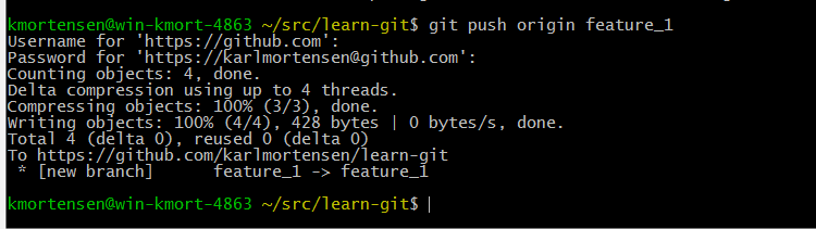
Now, having reviewed all my work and decided it's worthy, I "push" it to my origin with the following command: "git push origin feature_1"
As you can see on the GitHub website, it recognized that I pushed a change up to GitHub. This went to my "origin" (karlmortensen's fork).
Now, I'm going to do a "pull request" to tell the administrator of the master project that "hey, here's a good change for you to pull into the main repo." Do this with the GitHub website by clicking "Compare and Pull Request", then clicking "Create Pull Request" after it tells you that it's able to merge. The pull request will sit out there until acted upon by the master administrator, who gets an email asking him to merge the pull request into the master repo.
As the administrator, I accepted the pull request and merged the change into the repo. Now, everyone who forks the repo will get these changes as part of their repo. Everyone who updates their fork will get these changes too.
Now, I use the command "git checkout master" to switch back to the master branch, and guess what, my changes aren't there!
Have no fear, this is by design. See, we did the work in the "feature_1" branch, and we just switched over to a branch where this work has not been done. So let's pull these changes from the master so we can be up-to-date with the latest-greatest. We use two commands to do this: "git fetch upstream" and "git merge upstream/master"
The first command pulls the upstream repo down to the local machine, and the second merges in all the changes to the local copy of the upstream in the master branch. As if that's not confusing at all. Whew. The long and short of it is you are now up to date in your "master" branch on your local machine.
That's enough for tonight. Tomorrow we discuss other branches.
25 March 2014
Mechanical Integration
Mechanical integration came next. I got a bunch of nylon standoffs, nylon screws, and zip ties and set off to make the electrical stack on my quadcopter stick together and stay attached to the frame. This is important, as if your flight controller jiggles around with respect to the frame during the flight, your gyros, accelerometers, and magnetic compass are all going to be giving inaccurate readings about the orientation of the quadcopter’s frame. So it has to stay fixed.
Constraints:
- I want the GPS antenna to end up on top.
- My GPS board has an antenna covering one of the two through-holes, and mostly covering the other.
- The GPS board is about 2/3rds the size of the flight controller. This means you can’t reach the other side with standoffs
- The serial (UART) breakout board is about 2/3rds the size of the flight controller. This still means you can’t reach the other side with standoffs
- The antenna for the receiver needs to be available from the ground when the bird is flying
- The antenna for the 433 MHz link needs to be available from the ground when the bird is flying
- There is a reset button on the flight controller that would be nice to have available.
- There are indicator lights on the flight controller that I need to see when starting up.
- The antennas and wires must not get in the way of the propellers
I tried to think of some Lego-style combination of 2/3rds and 2/3rds that would allow me to combine the serial breakout board and the GPS board and use the far outside corners of the flight controller to hook into, but I didn’t come up with anything that worked.
I attached the flight controller to the frame with 13mm standoffs. I then loosely attached the serial breakout board to the flight controller with one screw on one 13mm standoffs, and let the other three sides float. Two of them have standoffs that are just resting on top of the flight controller board. While this is not great, the serial breakout board doesn’t have any orientation-sensing devices in it, so this is okay, as long as it stays mechanically attached. I also wonder if shock and vibration will eventually hurt the flight controller, but we’re a long way from there, I hope. :-)

To attach the GPS board to the serial breakout board, I had to modify some of the nylon standoffs. Nylon is an absolute dream to work with, as it is so easy to modify. All I did was grab some snips and a file, cut what I wanted, file off any sharp points, and it was good to go. Wear eye protection when you cut standoff threads with snips. They fly!

Nylon-working Tools
I cut down one standoff so I could just barely get a nylon nut on it. The other I cut just long enough to get the threaded part to stick up through the hole in the GPS board but not hit the antenna. See picture below.

The odd standoff configuration I used.
I then decided that I needed to protect the 433MHz 3DR radio, so I put some heatshrink on both sides.
Below, you can see before and after for the quadcopter’s end. I didn’t take a before picture of the laptop end.

433 MHz "3DR" Radio Mobile Side Front

433 MHz "3DR" Radio Mobile Side Back

433 MHz "3DR" Radios With Heat Shrink

Mobile Side Wiring and Antenna Attached
I put two layers of heat shrink on the laptop end of the radio. Note that I was silly and didn’t poke any holes for LEDs to shine through, so I’m kind of unaware if the USB end is ready. But you can see through the white shrinkwrap on the quadcopter’s end, so that’s a plus.

Laptop Side of the "3DR" Radio
Here is what the final stackup looked like:

Yes, the serial breakout board and the GPS board are not attached super well, but it should be okay.
In the end I wished for some 20-ish millimeter standoffs instead of my 13mm and 31mm. But it worked out okay.
With the standoffs placed how they are, one of them that is just floating on the flight controller board actually lights up with one of the status LEDs, which is kind of nice. In the pictures below you can see it when it’s red, and when it’s green.


Also, in the picture above, at the bottom left, you can see the 3DR radio zip tied to the frame below the power board, above where the battery connects. Zip ties are almost magical. :-)
What does the full thing look like? See below:

Note in the above picture you can see the Receiver zip tied to the frame as well. It's on the bottom left of the electronic's nest in the center, with a gray/red antenna wire hanging down. This enables it to receive signals from the ground station while it's in the air and still be out of the way of the propellers.
Strap a battery on the bottom with Velcro, and mechanically, he’s ready to fly!
06 March 2014
Integrating the GPS and Telemetry Radio
This rather simple post is about integrating the GPS and telemetry radio (often called a 3DR radio, which is a company that makes them. It's kind of like calling all telephones GrahamBells...).
I used a UART breakout board to do this, which made it spectacularly easy, if you ignore the silliness of me frying the VCC line to the serial connector.
You do not have to use a UART breakout board! You can simply modify the cable harness between your flight controller and your GPS & radio. I chose the easy way (UART breakout) for this prototype. Certainly you do not have to, but it was terrifically easy with it. When I got the proper power to it (5V), it was as simple as plug it in and wait for a GPS fix.
It was just as easy for the telemetry radio. It was super easy, as I had already supplied 5V to the connector via the bus wire from the I2C port. I had a concern about pulling so much power through one pin, but it's not on the Atmel AVR, so it should be fine. Anyway, I simply installed the driver for the 433 MHz telemetry radio on my Windows 7 laptop, told Mission Planner that I was using a 3DR, and tried to connect. I neglected to adjust the baud rate the first time, but once I set it to Autodetect, the baud rate adjusted and everything worked just fine. So suddenly, I am able to get a 3D GPS fix, and use remote telemetry with Mission Planner with minimal effort. I can move my quadcopter around and see the results on my laptop without a physical tether. We're getting somewhere. This is awesome.
Here's a picture I found somewhere on the web showing the overall idea:

The next step is to mechanically integrate the boards. See you next post.
25 February 2014
More Parts
In January, I ordered a few more parts from HobbyKing to help with the mechanical construction, now that the electrical things were working well. I guess they had some major problems, because it took 36 days to arrive. Now that I have the parts, I'll be doing the mechanical work in the very near future, so expect good things to come.
New Parts List:
The SD Card Reader/Writer will allow me to log data onboard for further analysis later. In the next few days I will be building the mechanical stack and we'll be into full-flying mode then!
New Parts List:
| Part Number | Part Description | |
|---|---|---|
| 1 | #HS-160A | Cable Ties |
| 2 | #OR009-01502 | M3 Nylon Nuts |
| 3 | #OR009-00503 | M3 Nylon Screws |
| 4 | #9171000168 | M3 Nylon Spacers (31 MM Standoff) |
| 5 | #9171000162 | M3 Nylon Spacers (13 MM Standoff) |
| 6 | #438000014 | SD Card Reader/Writer |
| 7 | #258000062 | 120 MM F to F Jumper Cables |
| 8 | #9171000186 | Pin Headers 2.54 MM Pitch |
The SD Card Reader/Writer will allow me to log data onboard for further analysis later. In the next few days I will be building the mechanical stack and we'll be into full-flying mode then!
27 January 2014
Compiling and Uploading MegaPirateNG Firmware to the Quadcopter
The following is the bare minimum to compile and upload the MegaPirateNG firmware to your Flight Controller. Refer to this site for the full tutorial.
The bare minimum highlights:
1) Download the source code. Circa January 2014, I used ArduCopter-MPNG V3.0.1 R2.
2) You need a special version of the Arduino environment. I used this one.
3) There is a step where you replace the Arduino environment's "pde.jar" with the one that comes with the MegaPirateNG source code. Do not skip this step. Make sure to do it with the Arduino IDE closed.
4) Open "ArduCopter.pde" in the Arduino IDE.
5) If you use the Hobby King V2 Flight Controller like I did, you need to modify the firmware, as this board does not use Pulse Position Modulation (PPM), but used Pulse Width Modulation (PWM) instead. The change to the firmware is minor, and shown below. Dig in and find the file ardupilot-mpng\libraries\AP_HAL_MPNG\RCInput_MPNG.cpp and modify it as shown in the pictures below. Red text is removed, and green text is added.
This is what the firmware looks like before the change:

This is what the firmware should look like after you have made the change to use PWM.

6) Install the Virtual COM Port (VCP) version of the FTDI driver. There are other versions, so check this page if you're not using Windows 7 64-bit like I am.
7) Hook up your Flight Controller via USB. Windows should recognize it and you should get some red blinking lights on the Flight Controller board.
8) Choose the proper serial port. Mine was COM3. Yours may be different.

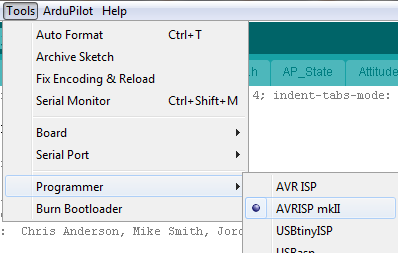
9) Choose the proper programmer. AVRISP mkII worked for me.
10) Choose the proper target board. My Flight Controller has an ATMega 2560 onboard.

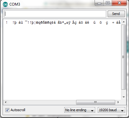
11) If you open the Serial Monitor under Tools, you should see some output coming from the board every second or so. Don't worry that it looks like gibberish at the moment. (We'll talk about that gibberish more next time.) See picture below.
12) Compile
To start the compilation:

Compiling:

Done Compiling:

13) Upload. Push this button while connected to upload. Be patient; it's a big sketch.

14 When the upload successfully completes, you should be able to open Mission Planner and connect. This is a tremendously awesome free GUI for configuring, controlling, and monitoring your quadcopter. We will get more in to this next time, but for you overachievers out there, feel free to go ahead.. You should be able to see all sorts of cool output from your connected flight controller. We're almost ready to arm and spin the motors.
The bare minimum highlights:
1) Download the source code. Circa January 2014, I used ArduCopter-MPNG V3.0.1 R2.
2) You need a special version of the Arduino environment. I used this one.
3) There is a step where you replace the Arduino environment's "pde.jar" with the one that comes with the MegaPirateNG source code. Do not skip this step. Make sure to do it with the Arduino IDE closed.
4) Open "ArduCopter.pde" in the Arduino IDE.
5) If you use the Hobby King V2 Flight Controller like I did, you need to modify the firmware, as this board does not use Pulse Position Modulation (PPM), but used Pulse Width Modulation (PWM) instead. The change to the firmware is minor, and shown below. Dig in and find the file ardupilot-mpng\libraries\AP_HAL_MPNG\RCInput_MPNG.cpp and modify it as shown in the pictures below. Red text is removed, and green text is added.
This is what the firmware looks like before the change:
This is what the firmware should look like after you have made the change to use PWM.
6) Install the Virtual COM Port (VCP) version of the FTDI driver. There are other versions, so check this page if you're not using Windows 7 64-bit like I am.
7) Hook up your Flight Controller via USB. Windows should recognize it and you should get some red blinking lights on the Flight Controller board.
8) Choose the proper serial port. Mine was COM3. Yours may be different.
9) Choose the proper programmer. AVRISP mkII worked for me.
10) Choose the proper target board. My Flight Controller has an ATMega 2560 onboard.
11) If you open the Serial Monitor under Tools, you should see some output coming from the board every second or so. Don't worry that it looks like gibberish at the moment. (We'll talk about that gibberish more next time.) See picture below.
12) Compile
To start the compilation:
Compiling:
Done Compiling:
13) Upload. Push this button while connected to upload. Be patient; it's a big sketch.
14 When the upload successfully completes, you should be able to open Mission Planner and connect. This is a tremendously awesome free GUI for configuring, controlling, and monitoring your quadcopter. We will get more in to this next time, but for you overachievers out there, feel free to go ahead.. You should be able to see all sorts of cool output from your connected flight controller. We're almost ready to arm and spin the motors.
19 January 2014
Calibrating ESC's
Before you can fly, you have to teach your Electronic Speed Controllers (ESC's) the minimum and maximum throttle levels they can expect to see. This is called ESC Calibration.
The way I did it the first time, I calibrated each ESC separately. I used my receiver and transmitter to do this. I learned all about ESC Calibration from this link. Truth be told, their page is better than mine. But this will be enough notes for me to repeat it in the future, so away we go. As we go on, remember, on the receiver the signal pin is the pin closest to the channel labels. The positive pin is in the middle, and the ground pin is on the outside.
1) Hook up the receiver to the ESC to be calibrated. Pick your throttle channel to plug in to, and make sure to plug in to the signal pin.
2) Turn the power on the transmitter on.
3) Put the transmitter to full throttle.
4) Turn the power to the ESC on
You will hear some musical tones first, then two beeps.
Gently slide the throttle all the way down. Wait for a few more beeps (one for each of the number of cells in your LiPo, I've been told.), and then one final longer beep. When the long beep stops, you can use the throttle to control the motor. If it behaves right, it's calibrated. You just taught the ESC how far from the off position to the full throttle position and everything in between.
5) Repeat for each ESC you need to calibrate.

The way I did it the first time, I calibrated each ESC separately. I used my receiver and transmitter to do this. I learned all about ESC Calibration from this link. Truth be told, their page is better than mine. But this will be enough notes for me to repeat it in the future, so away we go. As we go on, remember, on the receiver the signal pin is the pin closest to the channel labels. The positive pin is in the middle, and the ground pin is on the outside.
The Long Way
To calibrate these critters (mine are "Detrum Electronic Speed Controller Brushless Motor 5-18 NC/2-6 LIXX"), here is the process:1) Hook up the receiver to the ESC to be calibrated. Pick your throttle channel to plug in to, and make sure to plug in to the signal pin.
2) Turn the power on the transmitter on.
3) Put the transmitter to full throttle.
4) Turn the power to the ESC on
You will hear some musical tones first, then two beeps.
Gently slide the throttle all the way down. Wait for a few more beeps (one for each of the number of cells in your LiPo, I've been told.), and then one final longer beep. When the long beep stops, you can use the throttle to control the motor. If it behaves right, it's calibrated. You just taught the ESC how far from the off position to the full throttle position and everything in between.
5) Repeat for each ESC you need to calibrate.
The Easy Way
Once you have all your ESC's in the right region to respond to your transmitter, and you have hooked up your flight controller in its final configuration and programmed it with firmware (Don't worry, we'll get there!), you can do an All-At-Once ESC calibration. This gets all the ESCs programmed to the same level, instead of the small variations that can occur when you calibrate them individually. Note this didn't work for me before I programmed my ESCs individually. The ESCs have to be set near enough to the right range that none of them complain about the input level when you turn it on the first time.
The picture below is what one of my ESCs looks like. It has three wires going to the motor, as it's a three-phase brushless outrider motor. It also has lower power lines going to the Flight Controller, Signal, VCC and GND. It has a linear power regulator inside it. This means it hooks up to the LiPo directly, provides power to the motor through that, but regulates it down to around 5V for the Signal, VCC, and GND lines. You can power your Flight Controller off this power, but the folks at electronics.stackexchange.com suggest you don't do that, as the power out of the Battery Elimination Circuit (BEC) inside the ESC can be noisy, and the linear regulator is wasteful with power.
The picture below is what one of my ESCs looks like. It has three wires going to the motor, as it's a three-phase brushless outrider motor. It also has lower power lines going to the Flight Controller, Signal, VCC and GND. It has a linear power regulator inside it. This means it hooks up to the LiPo directly, provides power to the motor through that, but regulates it down to around 5V for the Signal, VCC, and GND lines. You can power your Flight Controller off this power, but the folks at electronics.stackexchange.com suggest you don't do that, as the power out of the Battery Elimination Circuit (BEC) inside the ESC can be noisy, and the linear regulator is wasteful with power.
To do an All-At-Once calibration, simply hook up your flight controller and receiver as described in an earlier post.
Then:
1) Turn on your transmitter
2) Throttle all the way up on the transmitter
3) Turn on power to your quadcopter
4) Wait for musical tones and two beeps (this should happen for each ESC simultaneously)
5) Bring throttle all the way down
6) Wait for some beeps and one long beep to signify the values are written out. The number of non-long beeps you get here is supposed to be the number of cells in your LiPo battery. Worked for me.
7) Test if raising the throttle spins the motors. If it does, you're done.
The nice thing about this is it calibrates them all evenly, which is very helpful. When I had done them individually, I had some motors that would spin when throttle was barely applied and some that would not. It was obvious that the throttle was not being evenly applied. When I recalibrated all at once, this became even. I think it matters if you have your flight controller firmly mounted in it's final mechanical configuration or not when you do this, but I haven't tested for certain. It seemed to.
17 January 2014
Receiver to Flight Controller
The flight controller is the brains of the quadcopter. It has sensors that determine the pitch, roll, yaw, altitude, and acceleration of the quadcopter. Mechanically fix the flight controller to the frame, tell the flight controller what level looks like based on how you mounted it to the frame, and tell it how your motors are arranged. (We will cover these things a bit later.) The flight controller senses if the quadcopter tips, and controls the motors to correct it and level out the quadcopter. Quite frankly, this is amazing. It takes a lot of the complication of flying out, and makes it stable and easy to fly.
In order to do this, the flight controller has to be hooked up to the receiver appropriately. There are six lines that matter for this:
1) Yaw
2) Throttle
3) Pitch
4) Roll
5) +5V
6) Ground
On the flight controller I bought, there is silk screen showing what to connect to where, but the silkscreen is wrong. The wrong labels are repeated on the hard case I bought. Pitch, Roll, and Throttle are wrong. Here is the wrong silkscreen on the flight controller board:

Here is the wrong silkscreen on the hard case.

It took me a long time to figure out that the silkscreen was wrong, as I completely trusted it. In the end, I was able to figure it out because when I tipped the quadcopter while it was turning the rotors on very low throttle, the wrong motors would cut out. The idea here is if you have it in a stabilize mode and you tip it so one rotor is up, that rotor should slow or stop because the unit is trying to level out. So experimentally, I determined the layout. Here's the actual layout for the board I have:
 Remember, the silkscreen is wrong, so it should read, starting with the yellow wire:
Yaw
Throttle
Pitch
Roll
+5V
Ground
As you can see above (spelled out for the colorblind), wire colors I chose are:
Yaw--Yellow
Throttle--White
Pitch--Blue
Roll--Red
+5V--Orange
Ground--Brown
These wires plug in to the receiver. Based on the color scheme I chose, and the channels I have selected on the transmitter, here is how I have wired up the receiver-flight controller connection at the receiver side:

Bat Orange and Brown (Inside has nothing, Middle is Orange, Outside is Brown)
6 White -- Throttle
5 Nothing
4 Yellow -- Yaw
3 Nothing
2 Blue -- Pitch
1 Red -- Roll
Remember that the signal pins are the inside ones (the pins nearest the channel number label).
As I spent so much time debugging the Receiver to Flight controller, and thinking I had something wrong, I'm documenting the full interconnect. The sticks on my transmitter are set up like this:
The next thing to hook up is the ESC's to the motor controls on the Flight Controller. There are four of them, and you have to get the right one in the right place (you could modify the firmware to change which one plugs in where, but it's a lot easier in my mind to simply plug the right one in to the right place). Again, you have to experimentally determine which one is which. I chose the "+" configuration, so here is what it turned out to be for me:
Note that as odd as it seems, according to the silkscreen there is no "4" slot.
Front 6
Back 2
Right 5
Left 3
Looking back at this blog post, it doesn't seem nearly as hard as it was in real life. The hardest part was that I kept thinking I did something wrong on the receiver end because of the problem with the silkscreen. Now that I know how it should go, wiring this up could be really fast and painless. :-)
In order to do this, the flight controller has to be hooked up to the receiver appropriately. There are six lines that matter for this:
1) Yaw
2) Throttle
3) Pitch
4) Roll
5) +5V
6) Ground
On the flight controller I bought, there is silk screen showing what to connect to where, but the silkscreen is wrong. The wrong labels are repeated on the hard case I bought. Pitch, Roll, and Throttle are wrong. Here is the wrong silkscreen on the flight controller board:
Here is the wrong silkscreen on the hard case.
It took me a long time to figure out that the silkscreen was wrong, as I completely trusted it. In the end, I was able to figure it out because when I tipped the quadcopter while it was turning the rotors on very low throttle, the wrong motors would cut out. The idea here is if you have it in a stabilize mode and you tip it so one rotor is up, that rotor should slow or stop because the unit is trying to level out. So experimentally, I determined the layout. Here's the actual layout for the board I have:
Remember, the silkscreen is wrong, so it should read, starting with the yellow wire:Yaw
Throttle
Pitch
Roll
+5V
Ground
As you can see above (spelled out for the colorblind), wire colors I chose are:
Yaw--Yellow
Throttle--White
Pitch--Blue
Roll--Red
+5V--Orange
Ground--Brown
These wires plug in to the receiver. Based on the color scheme I chose, and the channels I have selected on the transmitter, here is how I have wired up the receiver-flight controller connection at the receiver side:
Bat Orange and Brown (Inside has nothing, Middle is Orange, Outside is Brown)
6 White -- Throttle
5 Nothing
4 Yellow -- Yaw
3 Nothing
2 Blue -- Pitch
1 Red -- Roll
Remember that the signal pins are the inside ones (the pins nearest the channel number label).
As I spent so much time debugging the Receiver to Flight controller, and thinking I had something wrong, I'm documenting the full interconnect. The sticks on my transmitter are set up like this:
- Pitch (Blue), Channel 2, left stick forward and back
- Yaw (Yellow), Channel 4, left stick left and right
- Throttle (White), Channel 6, right stick forward and back
- Roll (Red), Channel 1, right stick left and right
The next thing to hook up is the ESC's to the motor controls on the Flight Controller. There are four of them, and you have to get the right one in the right place (you could modify the firmware to change which one plugs in where, but it's a lot easier in my mind to simply plug the right one in to the right place). Again, you have to experimentally determine which one is which. I chose the "+" configuration, so here is what it turned out to be for me:
Note that as odd as it seems, according to the silkscreen there is no "4" slot.
Front 6
Back 2
Right 5
Left 3
Looking back at this blog post, it doesn't seem nearly as hard as it was in real life. The hardest part was that I kept thinking I did something wrong on the receiver end because of the problem with the silkscreen. Now that I know how it should go, wiring this up could be really fast and painless. :-)
08 January 2014
Lessons Learned
Last post as I was trying to prove that the GPS worked after the board modifications, I couldn't get the USB connection to work with Mission Planner. I thought I had toasted my Flight Controller board yet again.
The COM port, COM3, had just disappeared from my laptop. Nothing I did could bring it back. I got an automatic Windows Update minutes before I plugged it in and it did not work. This was suspicious. I did a bunch of things to the PC to try to make it work:
After some thought, I realized that the power rails in a USB connector are longer than the signal rails. It makes sense that they are physically engaged before the signal rails are.
Silly me. In all my debugging, I had never reseated the Flight Controller end of the USB cable. I had done it all at the laptop end many times. One quick reseat and it was working fine. I did four things differently the time it worked. I'm listing them all, but I'm pretty sure it was that the USB connector wasn't all the way plugged in to the Flight Controller.
Differences:
I just wanted to mention it in case I'm wrong. One of those four things (or some odd combination plus reinstalling all the software above) did it. I'm reasonably confident it was reseating the USB cable at the Flight Controller.

The COM port, COM3, had just disappeared from my laptop. Nothing I did could bring it back. I got an automatic Windows Update minutes before I plugged it in and it did not work. This was suspicious. I did a bunch of things to the PC to try to make it work:
- I rebooted the PC multiple times
- Updated to the latest Mission Planner
- Reinstalled Mission Planner from scratch
- Reinstalled the Virtual COM Port driver
- Hard removed COM3 and reinstalled the Virtual COM Port driver
- Hard reinstalled FTDI drivers by themselves
- I thought that maybe I had connected it to a low-power USB port and there just wasn't quite enough juice to get it working. I tried all the USB ports on the laptop to no avail.
After some thought, I realized that the power rails in a USB connector are longer than the signal rails. It makes sense that they are physically engaged before the signal rails are.
Silly me. In all my debugging, I had never reseated the Flight Controller end of the USB cable. I had done it all at the laptop end many times. One quick reseat and it was working fine. I did four things differently the time it worked. I'm listing them all, but I'm pretty sure it was that the USB connector wasn't all the way plugged in to the Flight Controller.
Differences:
- Waited 20 minutes without anything plugged in (heat? built-up charge? gremlins?)
- Reseated the USB cable at the Flight Controller end
- I connected to the laptop via USB after connecting to the Flight Controller..... it really shouldn't matter.
- Held down the Flight Controller reset button while I plugged USB to the laptop, but I don't think that had anything to do with it.
I just wanted to mention it in case I'm wrong. One of those four things (or some odd combination plus reinstalling all the software above) did it. I'm reasonably confident it was reseating the USB cable at the Flight Controller.
So the long and short of it is that the Flight Controller fix made the GPS module work. This is good progress.
One thing that puzzles me is how good a GPS signal I get indoors. This is a cheap GPS module, but I'm seeing 7 satellites indoors. Can that be possible? The GPS units I use at work are orders of magnitude more expensive and nicer, and they take WAY longer to get a fix, and certainly can't function indoors. I'm wondering if this has something to do with the overall precision of the GPS unit. The ones at work claim to be very accurate when they have a fix. This one, not so much. Don't know. More on it later if I dig into it.
I thought that there was something else wrong with the Flight Controller, as I was unable to successfully arm it. Once I got it connected, I was able to use Mission Planner to figure out why it would not arm the ESCs. The error was "RC Not Calibrated". This means it did not think the Radio Control (Transmitter) was calibrated. I calibrated it and wrote the settings down to the Flight Controller, but it still came up as Not Calibrated each time I cycled power. I wondered if maybe the USB port wasn't kicking out enough power to write to the EEPROM or if there was something else wrong with the Flight Controller. After a lot of worry, it turns out that the trim for the throttle was WAY too high. This meant that even at the stick's minimum it couldn't get low enough for Mission Planner to be happy with it. I actually have two trims on my Transmitter, one a fine control, one a gross control. Apparently the gross control had been turned a lot. After fixing that, it armed no problems.
Next time we'll cover connecting the Flight Controller to the Receiver.
07 January 2014
Flight Controller Oops!
Large current sources and toddlers don't mix in happy ways.
Short story: My two year old helped me burn a flight controller trace right out of the board. It's fixed now.

In the course of my investigation, I was using a multimeter to see what was connected to what. In hindsight, it would have be a lot smarter to use the ohm-meter part of it rather than the volt-meter part, but oh well. I was trying to see if I got 11V or 5V between the VCC and GND on the serial port connector. My two year old bumped me at the exact wrong time and I let the magic smoke out. Electronics don't work very well once the magic smoke escapes. I shorted GND to VCC with my multimeter probe inside the serial port connector by making contact with both pins. It immediately sparked, burned, gave off smoke, and left me feeling less than smart. Take a look at the burned trace below.
.jpg)
.jpg)
Short story: My two year old helped me burn a flight controller trace right out of the board. It's fixed now.
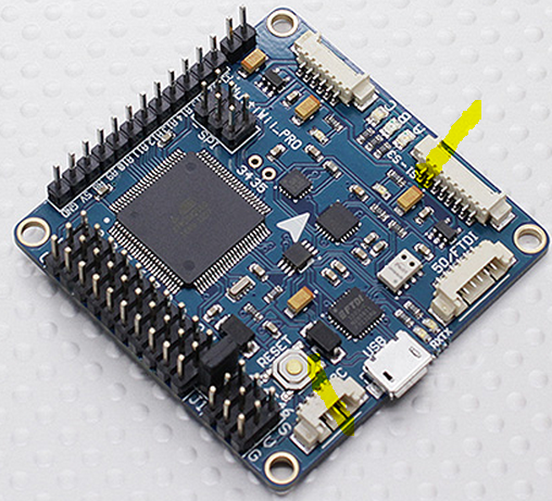
Longer story: I was trying to integrate the GPS and RF Radio (433 MHz for data, not the Receiver/Transmitter) to my flight controller and I didn't quite understand what was going on. When I plugged in via USB and powered VCC with 5V, everything worked just fine. When I powered the board with the LiPo (11V), the GPS did not work. I had thought that the connector holding serial port 1, 2, and 3 was powered from the 5V regulator, but this turns out not to be the case. It is directly connected to the pins shown below in yellow highlighter, labeled VCC and GND. In other words, the left yellow blob is connected to the right yellow blob. I power the Flight Controller with 11V on the top left yellow pins in the picture below. It gets regulated down to 5V, but not until after it hits the power on the connector for serial port 1, 2, and 3.
In the course of my investigation, I was using a multimeter to see what was connected to what. In hindsight, it would have be a lot smarter to use the ohm-meter part of it rather than the volt-meter part, but oh well. I was trying to see if I got 11V or 5V between the VCC and GND on the serial port connector. My two year old bumped me at the exact wrong time and I let the magic smoke out. Electronics don't work very well once the magic smoke escapes. I shorted GND to VCC with my multimeter probe inside the serial port connector by making contact with both pins. It immediately sparked, burned, gave off smoke, and left me feeling less than smart. Take a look at the burned trace below.
Near the top of this photo you can see the VCC line burned right out of the board, with a big chunk burned away. Interestingly enough, the GND trace burned, some of it was exposed at the top of the board, but it still had electrical continuity. Thankfully, the power traces appear to be on the outside of the board, so it didn't damage anything else. Everything else on the 5V side of the voltage regulator appears to be fine.
After some thought, I decided to route 5V from the I2C port to the Serial 1, 2, and 3 connector, as it is both regulated and does not go through the Atmel AVR microcontroller, which means there isn't nearly as big of a current draw concern. The screenshot below highlights in yellow the new intended connections.
I took the board in to the lab at work, as I don't have a big magnifying glass nor an awesome soldering iron (they have a seriously awesome one with super small tips). I tried to solder some bus wire from the I2C port to the Serial port for about 40 minutes without good success. The lab guys took pity on me, and about 18.5 seconds later, it was soldered on there good and tight. Thanks to Mike L. and Ben B. for getting me set up and soldering this. I'm not great with super-tiny details like this, but they knocked it out in a hurry. See the picture below for the completed patch, using red bus wire. It is glued down to the board to prevent mechanical stress on the soldering, as losing this wire means losing power to the GPS and the 433 MHz data radio on the quadcopter.
Testing with the GPS shows that everything is working as expected. This is the best of all possible mishaps, as it probably saved my GPS from getting burned up, and allowed me to route 5V to the appropriate places.
The only unfortunate thing is after all of this, Windows 7 and my flight controller are having some sort of disagreement. We're operating along with mission planner talking no problem, when suddenly, the serial port (VCP) goes away. Gone. Nothing left. I don't know why. Reboots and reinstalls haven't fixed it. I guess that's an issue for another day. For now, I'm just glad my GPS is (ostensibly) working. It looks like it based on status lights.... I can't prove it until I integrate the 433 MHz radio or get USB back up.
The only unfortunate thing is after all of this, Windows 7 and my flight controller are having some sort of disagreement. We're operating along with mission planner talking no problem, when suddenly, the serial port (VCP) goes away. Gone. Nothing left. I don't know why. Reboots and reinstalls haven't fixed it. I guess that's an issue for another day. For now, I'm just glad my GPS is (ostensibly) working. It looks like it based on status lights.... I can't prove it until I integrate the 433 MHz radio or get USB back up.
04 January 2014
Receiver/Transmitter Pair
The Receiver/Transmitter Pair is a radio set consisting of a Receiver and a Transmitter. The Transmitter has sticks, knobs, and buttons that allow you to control your quadcopter from the ground. The Receiver receives the radio frequency (RF) signals, interprets them, and passes them on to the Flight Controller.

Transmitter, shown above.

If you need more information, this video helped me figure out how to bind my transmitter to my receiver. It is not the greatest video ever, but it was helpful to me. I didn't know that the orange wire to my ESC was the signal wire, which he mentions.
The number of channels on your receiver is indicative of how many independent things you will be able to control at once. Mine is a 6 channel RX/TX (Receiver/Transmitter). This should be more than sufficient for a quadcopter.
The Frequency is the actual RF signal that you are transmitting and receiving on. Mine is 2.4 GHz (sometimes written 2400 MHz, they are the same). This is the same band as a lot of 802.11B (WIFI) equipment.

Transmitter, shown above.

Receiver and Bind Plug shown above
The signal pin is the pin closest to the labels. The positive pin is in the middle, and the ground pin is on the outside. This was actually hard to figure out, as the documentation seems hard to find on the web.
Pairing
When you first get your RX/TX hardware, you need to "pair" them. This associates them with each other very similar to what you do with a Bluetooth headset and phone. The hardware will come with a "Bind Plug" which is just a loopback cable that plugs in to the receiver to tell it to switch to Bind mode.
While individual hardware makers may have slightly different steps, this is what worked for me, and should be fairly applicable to the general case.
To Pair the Receiver/Transmitter
0) Start with no power applied anywhere
1) Plug the Bind Plug in to the "BATT" terminal.
2) Power up the receiver with 5 volts using any of the + and - terminals. You should see a blinking red light on the the receiver, indicating that it hasn't got signal from anywhere.
3) While holding down the "Bind Range Test" button on the transmitter, switch the transmitter power on. The light should go green on the transmitter, and solid red on the receiver. They are now Paired (or "Bound" if you like).
4) Turn off all power and remove the Bind Plug.
If you need more information, this video helped me figure out how to bind my transmitter to my receiver. It is not the greatest video ever, but it was helpful to me. I didn't know that the orange wire to my ESC was the signal wire, which he mentions.
Now that your transmitter is talking to your receiver, it's time to see what channel is what. If you have a servo or two, you can just plug them in to the different channels and map it out by trying the sticks and seeing which one is associated with which channel. Of course, you need to power the receiver with 5 volts applied to the "BATT" terminals.
If you don't have servos, there are more sophisticated things you can do. There is software that connects to the transmitter and allows you to see which channel is controlled by what stick/knob. The software also allows you to adjust which channel is where, how much the output varies when you push the sticks, and a lot of other things.
Item number 11 on my parts list is"#FS-L001/9043, Hobby King 2.4Ghz 6Ch Tx USB Cable". This cable hooks from the back of my transmitter to a USB port. I plugged it in to my PC and installed some driver software for it.
Configuration
One of my biggest complaints about Hobby King is the software on their web site is all USER SUPPLIED. Anybody could upload malware/virus/spyware/whatever. This is very unsettling. I recommend using this software inside a disposable Virtual Machine so that you don't risk your main machine.
On HobbyKing's web site there are four separate transmitter/receiver pairs that are ALMOST the same thing, but not quite, and of course different software has been uploaded for the different varieties. My particular controller is the 9042 Mode 1 (Mode 1 means the throttle stick is on the right--this page has some wonderful pictures of the modes), but the software that finally worked for me was from the 9042 Mode 2 page.
The parts I found from HobbyKing are at:
Go down to the purple "Files" tab to see the files you need. Again, these are uncontrolled, user-supplied files, so be careful. They could be wrong or worse.
From this page, I ended up installing:
- Virtual COM Port driver "CP210x_VCP_Windows"
- "Digital Radio software"
- "T6install" which installed a tool called "T6Config"
I needed the VCP software because it turns the USB into a virtual serial port, allowing the transmitter to talk straight across it to the software. It will create a virtual serial port that you hook the software to. In my case it was COM3.
Both "Digital Radio Software" and "T6Config" worked, but I found the "Digital Radio Software" to be much nicer. I was able to see which channel was what, swap channels around like I wanted, and calibrate settings. Of course I only did this after wasting a lot of time by trying to jump ahead and getting nowhere. It turns out my transmitter came from the factory with a reversed throttle channel. This means that when I pushed up, it went down and vice-versa. Since I didn't know much yet, it took me a long while to figure out why my ESC's would not arm. This was why, and will be covered in more detail in a future post.
You can also use Mission Planner to figure out which channel does what, but you have to have things much more put together to do that, and it kind of obviates the need for mapping out the channels if your hardware is already hooked up right. But it is a good sanity check, and I will show this in a future post.
Stick Ranges and Calibration
You can calibrate the min and max range of the sticks using the software above. You don't need to do that right know, but know that you can and that we will very likely come back to it later.
RX/TX Range
Before flying, I highly recommend checking out how far your receiver/transmitter pair can be from each other and consistently talk to each other. Do this on the ground. Kelly and I did not do this for the first flight test, and I think this might have been the cause of the crash (we have determined it was not the battery).
To do this, get a servo, a battery, a buddy, and a cell phone. Have the buddy move the appropriate transmitter knob and see if your servo responds. Keep moving farther away from the transmitter until it stops working. Document this and be careful to fly inside this range. Remember to consider altitude when figuring out safe ranges. You can set up failsafes and geofences, but more on that later. Much later actually.
One last thing: Here is a thread that talks more about the type of transmitter I have.
One last thing: Here is a thread that talks more about the type of transmitter I have.
Subscribe to:
Posts
(
Atom
)